INTERACTIVE ASSEMBLY
Wire the D latch
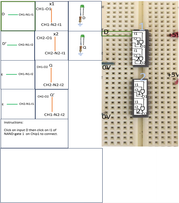
LIVE SIMULATION
Test the completed latch
Inputs
Set the data input and enable signal. When E = 1, Q follows D. When E = 0, Q holds its previous value.
Data (D)
Enable (E)
Join the physical-lab queue to control the real circuit. You can watch at any time.
Physical controls connect when the Raspberry Pi control service is running.
CURRENT OUTPUT
Q0
Q′1
The latch is holding its initial value because E = 0.
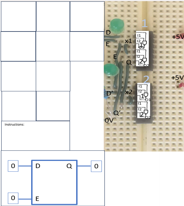
PHYSICAL LAB CAMERA
Lab live stream
Watch the real circuit while you test the simulated latch.
Secure live view of the physical lab hardware.
CONTROLLED LEARNING STUDY